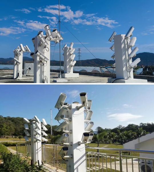
MIOS-Optical Subsystem:
The MIOS multi-station optical subsystem is located at Ledong (18.4°N, 109°E) and Sanya (18.3°N, 109.6°E) which are separated by 70 km. It consists of 24 (23) low-light-level cameras (type Watec 902 H2 Ultimate) equipped with narrow field f/0.95 lenses, and 2 (2) cameras equipped with wide field f/1.2 lens at Ledong (Sanya). The video data of meteor events recorded by the narrow field cameras are automatically processed and the meteor parameters including occurrence time, visual magnitude, and angular position are obtained in nearly real time for quick view. Six cameras equipped with 600 lines/mm gratings and f/0.95 lens were installed at Ledong (more spectral cameras are planned at Sanya) to record the spectra of relatively bright meteors. The spectral range is about 350-950 nm, with the resolutions ranging approximately between 0.2 and 2 nm/pixel (for different cameras with different focal lengths). To keep the consistency in time for meteor events recorded by different cameras of the MIOS, each video frame is time stamped by tracking the GPS signal. The position of meteor trajectory can be obtained from simultaneous observations by the cameras at Ledong and Sanya with the plane-plane intersection method.
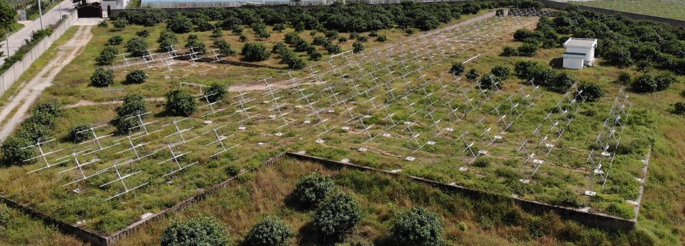
MIOS-Radar Subsystem:
The MIOS radar subsystem employs an active phased array consisting of 135 three-element Yagi antennas. Each antenna, with a reflector (3.2 m length), a driven element (2.964 m length), and a director (2.612 m length) has a gain of 8.6 dBi centered on 47.5 MHz. The phased array is divided into 15 identical subarrays arranged in an area shaped like a sword and Each subarray includes 9 antennas arranged in a square structure. This antenna configuration enables long baseline imaging measurements and unambiguous interferometry measurements using the crossed subarrays. The transceiver consists of a digital receiver, RF receiver, and digital exciter. The digital exciter can take external clock and timing signals from the GPS Disciplined Oscillator (GPSDO), which provides a capability for synchronization with other observations. The RF signal from each T/R module is input to a 1:3 splitter/combiner module and further divided into three RF signals, and then fed to three antennas for radiation. Only six subarrays are employed for transmission, with two options: the subarrays numbered 1-6 with half power beam width of 30° in elevation 8° in azimuth and the subarrays numbered 1-2 and 7-10 and with half power beam width of 10° in elevation and 24° in azimuth. For the reception, the RF signals from the three antennas of each group are combined through the splitter/combiner module, and then input to the T/R module, where the RF signal is controlled in phase-offset. Next, three phase-shifted RF signals (corresponding to one subarray) are combined into one RF signal and then input to the digital transceiver, where the RF signal is converted into IQ components and processed for obtaining echo spectra. The digital transceiver includes 15 channel signal processing units that allow the signals from the 15 subarrays are processed. Based on the simultaneous multi-channel IQ data, the spatial domain interferometric and imaging analysis can be performed. The MIOS-radar subsystem also incorporates an all-sky meteor radar (operational frequency of 38.9 MHz) to observe specular and non-specular meteor echoes from all-sky coverage.